schematic kubota wiring diagram pdf
Kubota wiring diagrams are essential for understanding and repairing electrical systems in Kubota tractors and equipment. These schematics provide detailed visual representations of circuits, components, and connections, ensuring safe and efficient troubleshooting and maintenance.

Understanding Kubota Wiring Diagrams
Kubota wiring diagrams provide a visual representation of electrical circuits, showing components, connections, and power distribution. They are essential for diagnosing issues and ensuring proper system function, with detailed schematics for safe and efficient repairs.
Symbols and Components in Kubota Wiring Diagrams
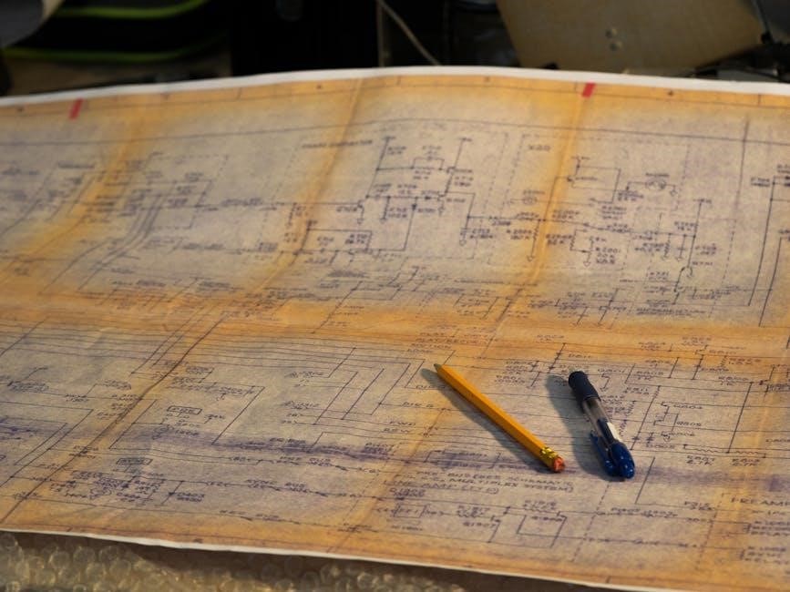
Understanding Kubota wiring diagrams begins with recognizing the symbols and components. Wires are typically represented by lines, while components like batteries, fuses, relays, and solenoids are depicted by specific shapes. Batteries are often shown as two parallel lines with a positive and negative terminal. Fuses are usually rectangular with lines inside, indicating their rating. Relays are illustrated with coils and contact points, showing how they control circuits. Solenoids may appear as coils with arrows, indicating their actuation direction.
Motors and other devices are often shown as circles or rectangles with internal details. Ground symbols, like a chassis or earth ground, are crucial for circuit completion. Abbreviations like “IGN” for ignition and “ACC” for accessories are common. Wire colors may follow standard codes, though a legend is essential for accurate interpretation. By mastering these symbols and their meanings, one can effectively trace circuits and diagnose issues in Kubota equipment.
How to Read a Kubota Wiring Diagram
Reading a Kubota wiring diagram requires a systematic approach. Start by identifying the legend or key, which explains the symbols and abbreviations used. Locate the power source, typically labeled as “BAT” or “VCC,” and trace the circuit flow through fuses, relays, and switches. Each component is represented by a specific symbol, such as a circle for a fuse or a rectangle with terminals for a relay.
Follow the wires, represented by lines, to understand connections between components. Color codes may be used to differentiate circuits. Ground points, often marked with a “GND” symbol, indicate where the circuit connects to the chassis or earth. Identify the load, such as lights or motors, and verify how they are controlled. Use the diagram to pinpoint potential failure points, like blown fuses or faulty connections. Always cross-reference with the tractor’s manual for specific details. By methodically tracing each circuit, you can diagnose and repair electrical issues efficiently.

Common Kubota Wiring Diagrams
Kubota wiring diagrams are available for various tractor models, including L-Series, B-Series, and ZD326 mowers. These diagrams detail electrical systems, circuits, and connections, aiding in troubleshooting and repairs. They are essential for understanding specific tractor configurations and ensuring proper functionality.

Kubota L-Series Tractor Wiring Diagrams
Kubota L-Series tractor wiring diagrams provide a comprehensive overview of the electrical systems for these versatile tractors. These diagrams detail the circuits, connectors, and components, making it easier to diagnose and repair issues. They cover essential systems such as lighting, ignition, and power distribution.
- They include detailed schematics for models like the L3830 and L4630.
- Diagrams highlight connections for hydraulic systems, PTO, and accessories.
- They are color-coded for clarity, distinguishing between power, ground, and signal wires.
These wiring diagrams are indispensable for technicians and DIY enthusiasts, ensuring proper functionality and safety when performing electrical repairs or upgrades on Kubota L-Series tractors.
Kubota B-Series Tractor Wiring Diagrams
Kubota B-Series tractor wiring diagrams are crucial for understanding the electrical systems of these compact and powerful tractors. These diagrams provide detailed schematics for models like the B219, B7800, and B3030, covering circuits, connectors, and components.

- They include specific wiring details for systems such as ignition, lighting, and power distribution.
- Diagrams often highlight connections for accessories like hydraulic systems, PTO, and loader operations.
- Color-coded wires are clearly marked, ensuring easy identification of power, ground, and signal lines.
These wiring diagrams are essential for technicians and enthusiasts alike, aiding in troubleshooting, repairs, and upgrades. They ensure proper functionality and safety when working with electrical systems on Kubota B-Series tractors.
Kubota ZD326 Mower Wiring Diagram
The Kubota ZD326 mower wiring diagram is a detailed schematic that outlines the electrical system of the ZD326 zero-turn mower. This diagram is essential for understanding the connections and components that power the machine’s functions, including ignition, lighting, and cutting deck operations.

- The diagram provides a clear layout of the wiring harness, highlighting key components like the ignition switch, fuel sensors, and electrical connectors.
- It includes specific details for the mower’s hydraulic systems and PTO (Power Take-Off) circuits, ensuring proper functionality and safety.
- Color-coded wires are used to differentiate between power, ground, and signal lines, making it easier to trace and diagnose issues.
By referring to the Kubota ZD326 wiring diagram, users can perform routine maintenance, troubleshoot electrical problems, and even upgrade their mower’s systems. It serves as an invaluable resource for both professionals and enthusiasts, ensuring optimal performance and longevity of the equipment.

Troubleshooting Electrical Issues with Kubota Wiring Diagrams
Kubota wiring diagrams are crucial for diagnosing electrical issues, allowing users to trace circuits and identify faulty components efficiently. They provide a clear visual layout, aiding in quick repairs and minimizing downtime.
Common Electrical Problems in Kubota Tractors
Kubota tractors, like any complex machinery, can experience electrical issues. Common problems include blown fuses, faulty alternators, and corroded or loose wiring connections. These issues often arise from exposure to harsh environments, such as moisture or extreme temperatures, which can degrade electrical components over time. Additionally, malfunctioning sensors or relays can disrupt critical systems, leading to operational failures. Another frequent issue is outdated or damaged wiring diagrams, which can make troubleshooting difficult. Improper installations or modifications to the electrical system can also introduce errors, emphasizing the importance of adhering to manufacturer guidelines. By referencing Kubota wiring diagrams, users can identify and isolate problematic areas, ensuring efficient repairs and minimizing downtime. Regular maintenance, such as cleaning connectors and inspecting wires, can help prevent these issues. Addressing electrical problems promptly is essential to maintain the tractor’s performance and longevity.
Using Kubota Wiring Diagrams for Diagnosis
Kubota wiring diagrams are invaluable tools for diagnosing electrical issues in tractors and equipment. These diagrams provide a visual representation of the electrical system, allowing users to identify faulty components, trace circuits, and understand how systems interact. By referencing the wiring diagram, technicians can pinpoint problems such as blown fuses, short circuits, or malfunctioning sensors. The diagrams also help users locate specific connectors, relays, and wiring harnesses, streamlining the troubleshooting process. For instance, if a tractor’s headlights fail, the wiring diagram can reveal whether the issue lies in the power supply, ground connection, or a faulty switch. Additionally, the diagrams enable users to test individual components, such as alternators or starter motors, ensuring accurate repairs. Regularly updating and cross-referencing with repair manuals can enhance diagnostic accuracy. By leveraging Kubota wiring diagrams, users can resolve electrical issues efficiently, minimizing downtime and ensuring optimal equipment performance.

Safety Tips When Working with Kubota Wiring Diagrams
When working with Kubota wiring diagrams, safety is paramount to prevent accidents and ensure effective repairs. Always disconnect the power source before starting any electrical work to avoid shocks or short circuits. Wear appropriate protective equipment, such as insulated gloves and safety glasses, to protect yourself from potential hazards. Never bypass fuses or relays, as this can lead to system overloads or fires. Use a multimeter to test circuits carefully, ensuring you follow proper measurement techniques. Avoid working in damp or wet conditions, as moisture can conduct electricity and increase the risk of shocks. Keep the wiring diagram nearby for reference, and double-check connections before restoring power. If unsure about a procedure, consult a professional or the official Kubota service manual. Properly label and organize wires to prevent confusion and future complications. By adhering to these guidelines, you can safely and effectively diagnose and repair electrical issues using Kubota wiring diagrams.

Resources for Kubota Wiring Diagrams
Kubota wiring diagrams are available in official service manuals, online marketplaces like Amazon, and Kubota’s official website. Authorized dealers and forums also provide access to these schematics, ensuring easy troubleshooting and repairs.
Where to Find Kubota Wiring Diagrams Online
Locating Kubota wiring diagrams online is straightforward, with multiple reliable sources available. Official Kubota websites and authorized dealers provide downloadable PDF versions of these schematics, often specific to tractor models like the L3830F or B7800. Additionally, online marketplaces such as Amazon and eBay offer wiring manuals for various Kubota tractors and equipment. Forums dedicated to Kubota enthusiasts are another valuable resource, where users share and discuss wiring diagrams. Websites specializing in tractor parts and repair manuals also host extensive libraries of Kubota wiring diagrams. When searching, using specific keywords like “schematic Kubota wiring diagram PDF” or “Kubota tractor wiring manual” yields accurate results. Always ensure the source is reputable to avoid incorrect or incomplete information. These resources are indispensable for DIY repairs and understanding complex electrical systems in Kubota machinery. Accessing these diagrams ensures efficient troubleshooting and maintenance for optimal performance.
Tools and Software for Editing Kubota Wiring Diagrams
Editing Kubota wiring diagrams requires specialized tools and software to ensure accuracy and professionalism. Popular options include Adobe Acrobat for modifying PDF files, while programs like AutoCAD or EPLAN are ideal for creating detailed electrical schematics. Online tools such as Lucidchart or SmartDraw offer user-friendly interfaces for designing and customizing wiring diagrams. For DIY enthusiasts, free software like Fritzing or KiCad can be used to create and edit circuit diagrams. Additionally, Kubota-specific software, such as the Kubota Diagnostic Tool, provides advanced features for troubleshooting and updating electrical systems. When editing diagrams, ensure compatibility with Kubota’s proprietary formats to maintain consistency. These tools enable users to modify, annotate, and enhance wiring diagrams for repair, customization, or documentation purposes. By leveraging the right software, individuals can create clear, functional, and precise diagrams tailored to their needs.


